Project Description
HAMMERSMITH BRIDGE
Introduction
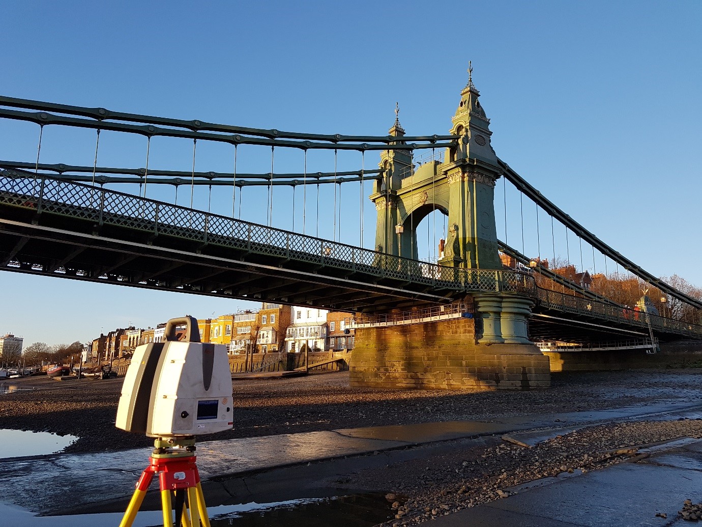
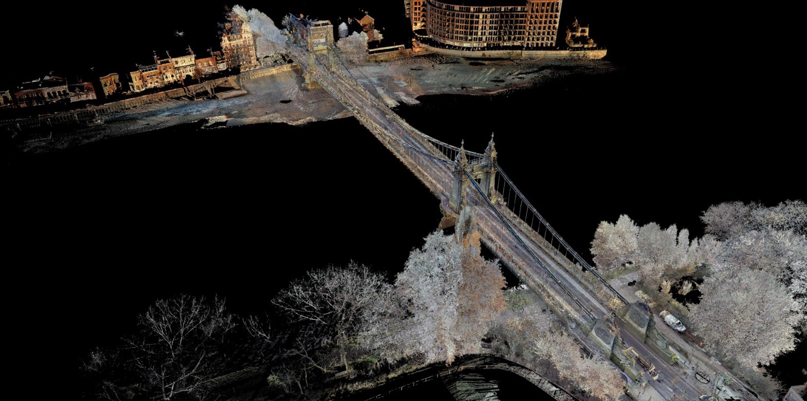
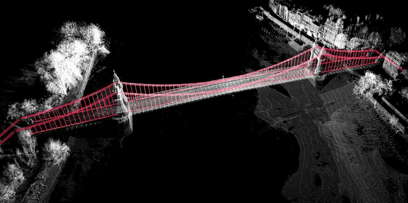
Hammersmith Bridge was constructed circa 1887 and is a Grade 2* listed structure. It crosses the River Thames and consists of 3 spans making a total length of 223m.
There are weight restrictions on the bridge, which affects traffic flow and it now requires a major overhaul, as some of the bridge elements need repair or renewal. TfL are also investigating strengthening the bridge to allow unrestricted double-decker bus access.
The structure is currently comprised of a timber deck bolted to cross girders, supported by longitudinal stiffening girders. The footway is a timber deck supported by wrought iron cantilever beams that connect both into the main cross girders and the stiffening girder. The deck structure is suspended on wrought iron hangers from parallel double suspension chains. The chains are connected to saddles, which slide on bearings (the original roller bearings now replaced with elastomeric bearings), on the top of the wrought iron towers. These chains then pass over abutment saddles, which are all housed inside ornamental cast iron casings to finally pass down sub-surface tunnels to the anchorage.
Methodology
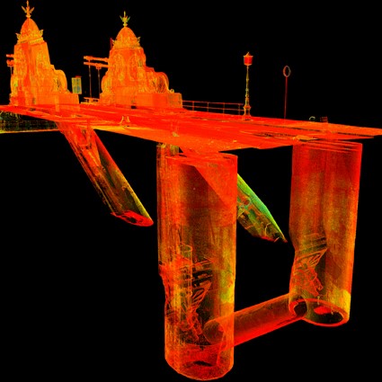
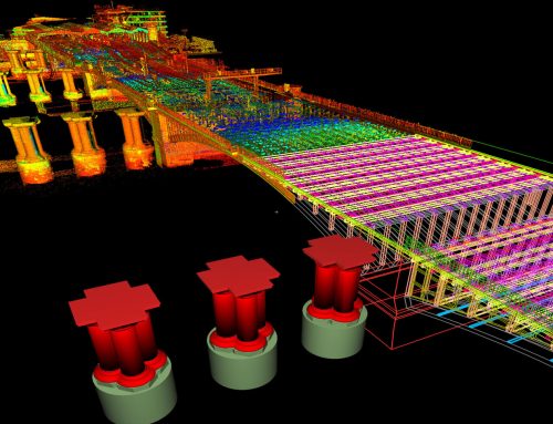
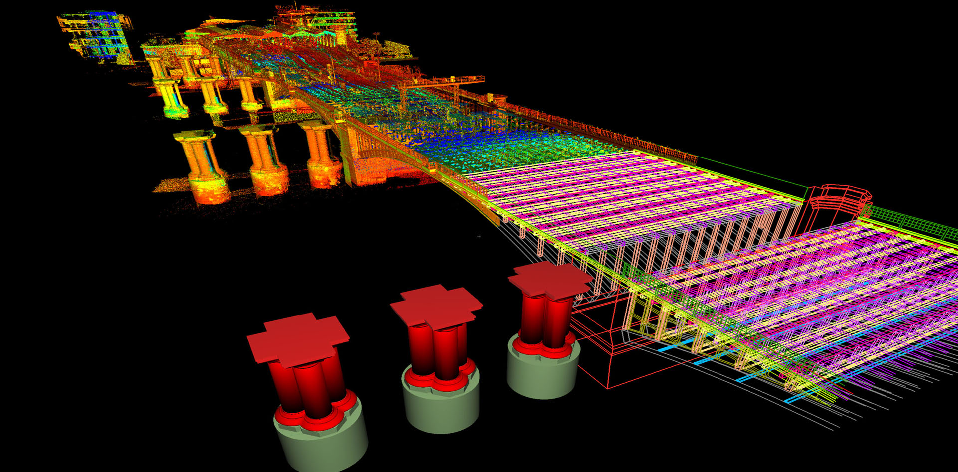
ABA Surveying were approached to survey Hammersmith Bridge and supply the principal contractor with a full pointcloud survey of the bridge (intensity and RGB) and a wireframe CAD drawing showing chain centre lines, hanger axis and truss chord surface centre lines to enable finite analysis exercises. The pointcloud was required at deck level and underside to show all structural girders, inside the chain tunnels, anchorages, towers, abutments and saddles.
ABA mobilised at short notice to take advantage of road closures and engineered an innovative solution to scan the underside of the structure.
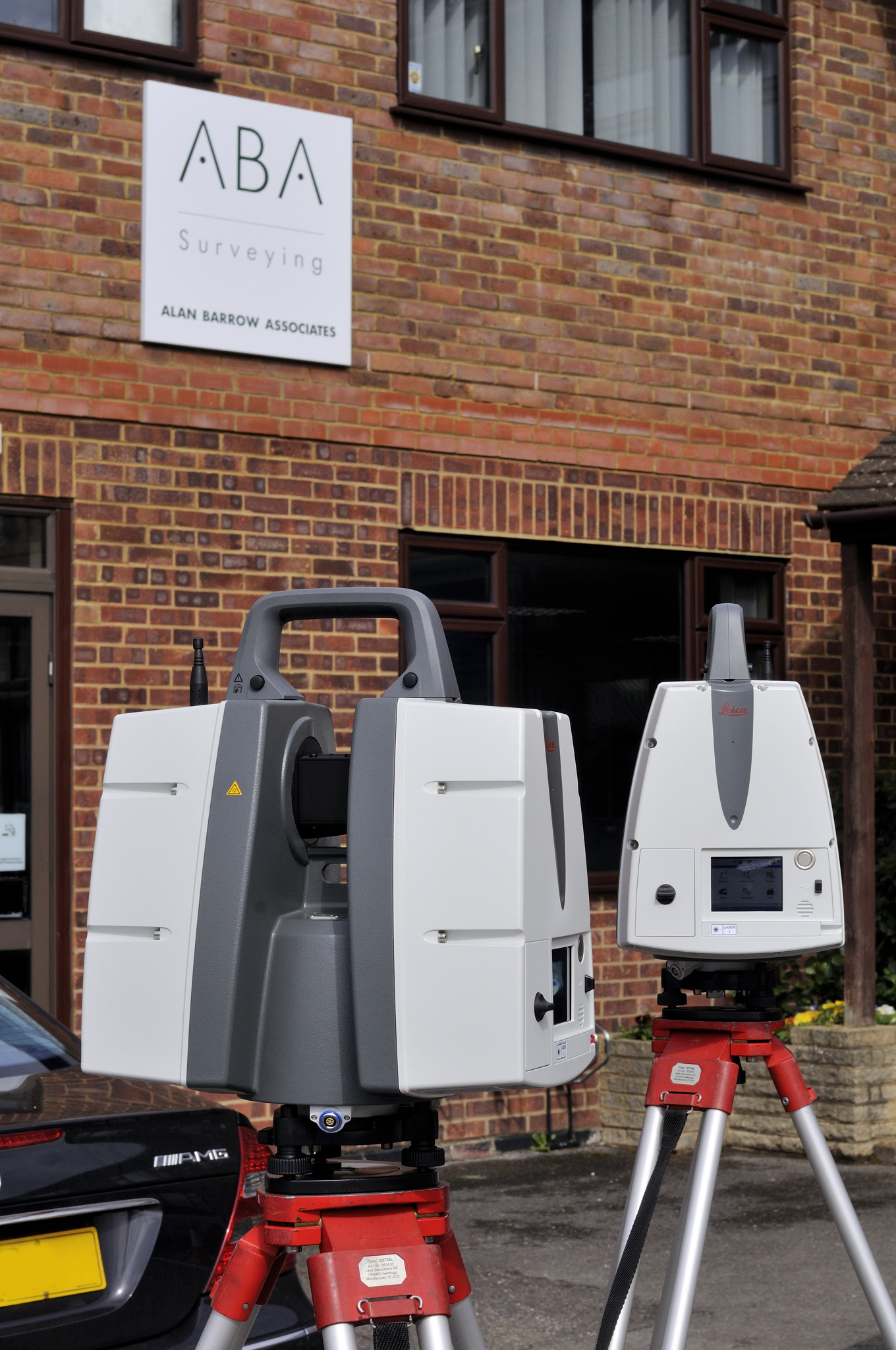
We used our two Leica P40 laser scanners to capture the pointcloud data for the bridge. Scan registration was completed in Cyclone and controlled using a mix of targets captured by total station and cloud to cloud registration.
In order to colourise the pointcloud with RGB, an iSTAR camera was used to generate panoramic images which were stitched to the cloud using Cyclone. Severe time restrictions and the option of HDR imagery required the use of an iSTAR, instead of the onboard scanner camera.
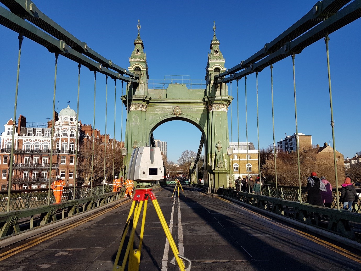
Access to the deck level and underside was restricted to programmed road closures when other work was scheduled. Apart from the time constraint, the deck level scanning was relatively straightforward.
Scanning the other areas brought up access and safety issues which required planning safe systems of work and using our confined space trained surveyors.
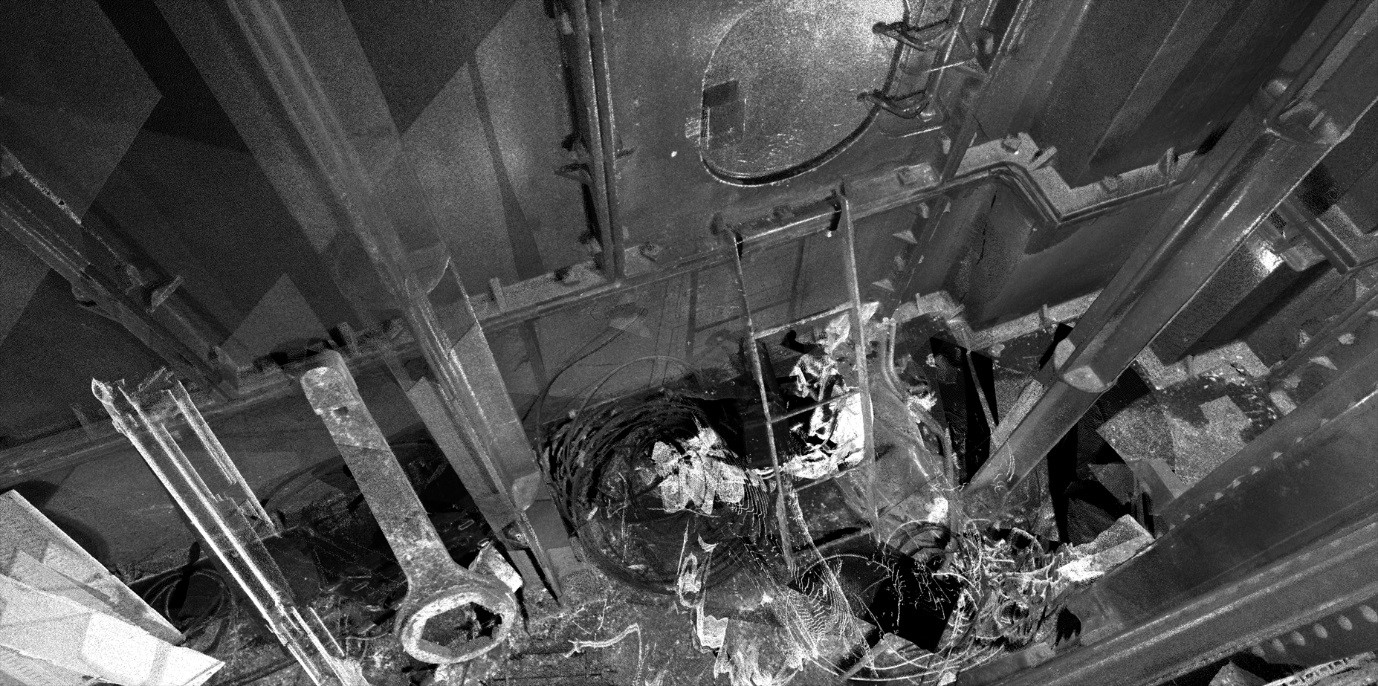
The chain tunnels and anchorages were flooded with water, which had to be pumped out and tested to ensure that it was a safe working environment. A specialist rope team then had to abseil into the chamber to ensure it was safe to enter. An initial inverted scan with the P40 was taken above the open manhole cover looking down, further scans were then taken from inside the chamber.
The chain tunnels were steeply sloped and did not have a lot of space within to work. Access was also gained via a manhole so further inverted scans were needed.
The towers were treated as confined spaces and also required working at height safety procedures. Access was gained through extremely small metal hatches and was physically demanding, negotiating our way up through the narrow walkways and ladders within the wrought iron tower structure.
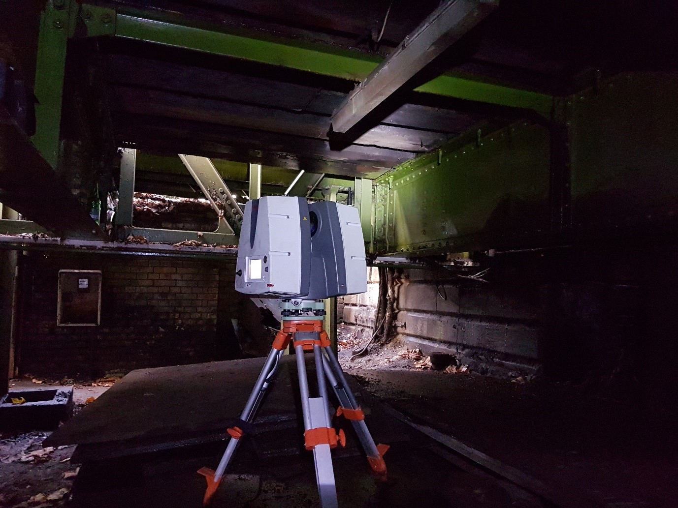
For the scanning of the underside of the bridge, a rigid bespoke rig was constructed to hold the scanner, which was moved along the bridge longitudinally, to ensure that all girders were captured and there were no occlusions. This built on our experience gained scanning the underside of Blackfriars Bridge in 2006 for Network Rail’s Thameslink programme.
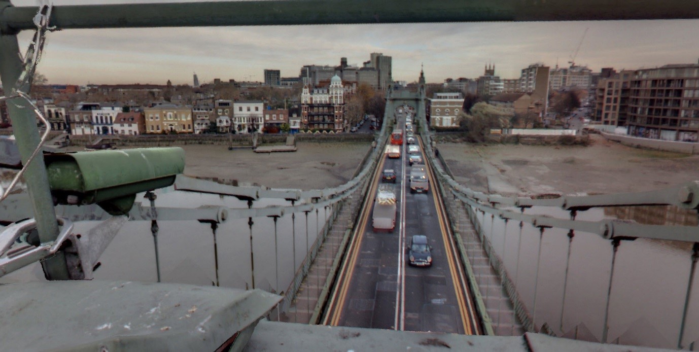
View from the Top of the South Tower
P40 on short Tripod for restricted headroom areas on the foreshore
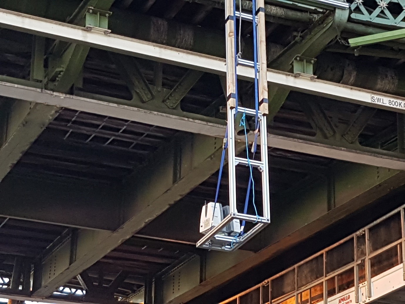
P40 mounted on bespoke rig to scan bridge underside
Tower access, note the size of the spanner for the chain bolts, not something you’d find in the average toolbox.
Results
A total of 534 static scans were captured over 3 shifts during the road closures and a small number of follow up visits to the towers and abutment areas, where access had to be coordinated with other agencies.
Back at the office, all pointcloud processing was undertaken in Cyclone. This included initial pointcloud processing, scan registration and modelling the location of the chain centre lines, hanger and truss chord axis.
After cleaning the pointcloud to remove unwanted artefacts, such as people and road cones, the pointcloud was supplied as RECAP, PTS and E57 files. The data together with the CAD linework were delivered on time.
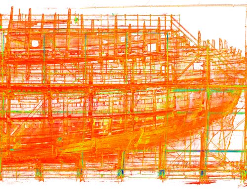
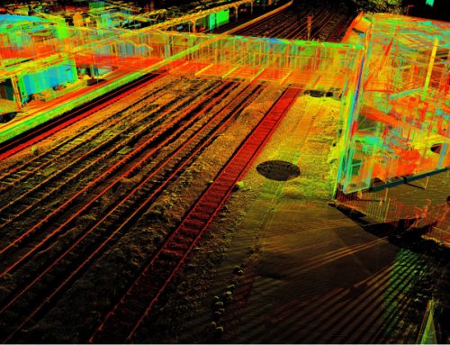
Intensity pointcloud of anchor chambers, chain tunnels and abutments.

Comparison of 1887 Bazalgette Design to As-Built 130 years later
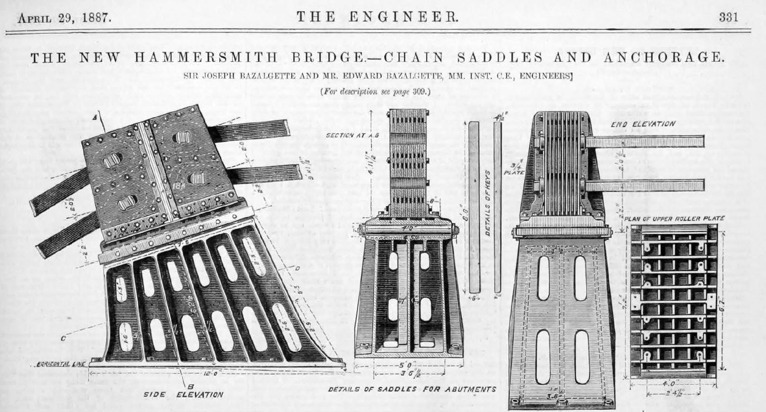
Bazalgette’s design drawings for the bridge were published in the April 29, 1887, edition of The Engineer.
It is interesting to compare a couple of dimensions from the present day pointcloud against these 1887 design drawings.
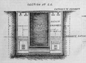 The centre lines of the Anchor Chambers are 30’ (9.144m) apart in the section shown in the original design drawings.
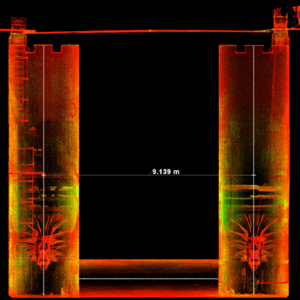 From the pointcloud a measurement of 9.139m was taken, a difference of 5mm
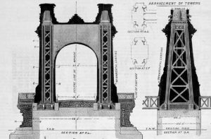 In the design drawings, a cross-section of a tower shows the width of the carriageway to be 19’9” (6.020m) and the distance between the centre lines for the iron structure inside the tower to be 30’ (9.144m).
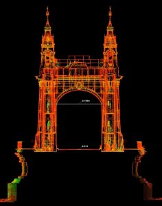
From the pointcloud, measurements of 6.014m and 9.152m were taken respectively.
Summary
ABA Surveying utilised it’s 18 years’ experience of laser scanning to survey the bridge and other critical areas within budget and on time. We had the necessary expertise and training to come up with solutions to scan the difficult to access areas. It was often necessary to deploy field staff at short notice to the site but we had the flexibility and resources available to do so.
Once the pointcloud was fully registered we were able to satisfy our client’s requests for information and back in the office it was also possible to extract additional client requests that had not been in the original remit, without the need for further site visits.
Acknowledgments
Bridge design drawings originally published in The Engineer courtesy of Grace’s Guide to British Industrial History.